In the last few years, I have decided that I needed a specialized
telescope, and that it was time to build it. The following links deal with
designing, building and using a homebuilt 12" ultra light dob, DS-3 (Deep
Space 3). Although this was my first amateur telescope making
adventure, it ended up working out quite well. Finally, I want to
give credit to my mentor and fellow ATM partner, Jim Lawrence.
Without Jim's help, as well as the advice of other members of the local
Albuquerque astronomy club (TAAS), this ultra light telescope would never
have been attempted. Links to Jim's telescope that served as a
prototype for DS-3, along with his ongoing work on binocular telescopes
can be found in the Astronomy Links section of this web site. Be
sure to check out his 300mm Telescope (my prototype) and his 300mm
Binocular (my dream scope, if it would fit into my car).
My latest project is a 12" travel telescope. It is
documented here: DS-Trill
I have recently completed a 16" Deep Space Scope. DS-4 is located here.
Design requirements of DS-3 were as follows:
Light weight. Weight of the heaviest single part of this lightweight
dob should be less than 30 pounds, and the total should be less than 50
pounds. This is necessary since I live in a second floor apartment, and
must carry the telescope upstairs each time I use it.
Small size. The telescope MUST fit in the trunk of my car, which is a
Honda Del Sol. I also want space left over for carrying my eyepiece box
and an observing chair. Why not buy a bigger vehicle?
See my web page on Peak Oil.
Large diameter mirror. Aperture rules for deep space! I want at least
a 10" (10 inch) primary mirror, and preferably a 12" primary mirror.
The primary mirror should be about f 5.0. From my experience, faster
telescopes have mirror costs go up disproportionately fast for a given
quality, and slower telescopes end up being too tall.
Height at the eyepiece. I wanted the height of the eyepiece to be less
than 60" when looking straight up, so that anyone could use the scope
without needing a ladder or step.
Setup time should be under 5 minutes. Setup of this truss dob
should require no tools and include a minimum amount of setup or tear
down.
As a secondary design goal, this scope should be cool looking!
Note - all pictures on this web site are
clickable and will bring up full size pictures.
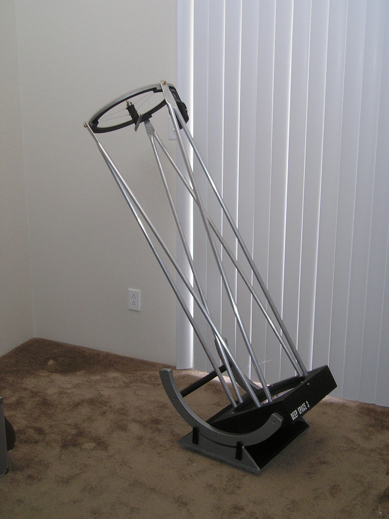
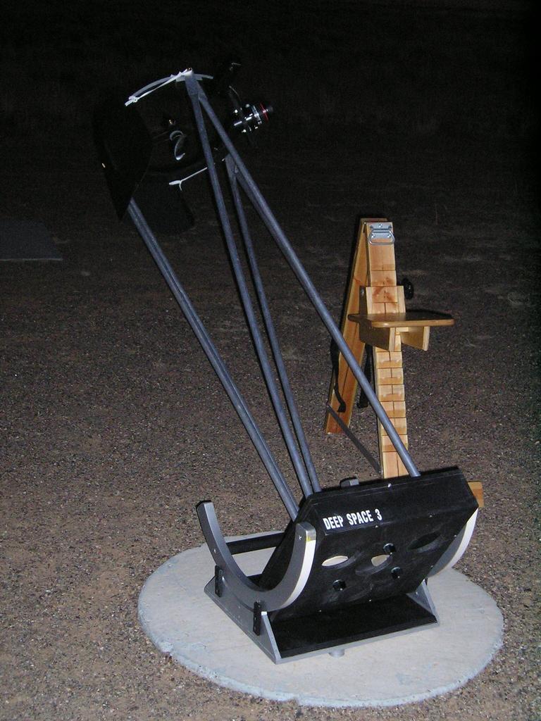
The finished product looks like this:
Two pictures of the completed truss scope, without baffling. DS-3
ready to play.
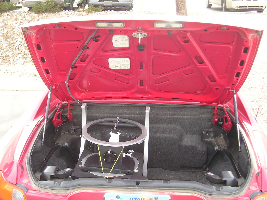
This lightweight dobsonian telescope torn down, and in the trunk of a
Honda Del Sol.
Final design specs (as of Dec 2004) are:
Primary mirror: 12" f5.0, 1 1/2" thick
Secondary mirror: 2.05"
Weight: Total weight, including trusses: 39 pounds
Weight of heaviest piece (Mirror box with mirror): 25 pounds
Weight of primary mirror and mirror cell: 14 pounds
Secondary cage weight: 2 pounds
Truss weight: 4 pounds
Base weight: 8 pounds
Height of eyepiece: 58.5"
Finder: Rigel Quick Finder
Focuser: KineOptics Helical Crayford HC-2, 2"
Packed size: width 17.5", length 21", height 19"
Size of this ultra light telescope if compressed for airline travel by
removing the bearings (approximate, without poles): width: 15.5", length
17.5", height 9"
Results - DS-3
under the stars - This web page describes how each section of
the telescope performed, along with my analysis of the whole.
Generally, results have been spectacular.
Design methodology
This homebuilt telescope was designed and built in the following order -
the primary mirror selection, primary box and mirror cell, secondary ring
and secondary cell, trusses, bearings, and last rocker box and ground
board.
Select the mirror. I knew from working with a friend that a 12"
lightweight telescope design would just fit my specifications. So, a 12"
f5.0 primary mirror was selected. This mirror size maximizes the amount
of light received, while still meeting my size and weight requirements.
This mirror is from Gary Hand at Hands On Optics, and is of very good
quality - as per numerous "old salts" in the local club.
Select the building materials. See below.
Design the telescope using NEWT.
I used NEWT(actually, it was NEWTWIN) to check clearances and
secondary mirror size. See NEWT Design below for details.
See Sources and Supplies below to get NEWT.
Design the mirror cell using PLOP.
OK, I didn't originally design the mirror cell using plop. I used
Jim Lawrence's experience and a good dose of common sense. As per
plop, I have about a 1/21 wave mirror cell. Not terribly bad, but
not good. See Plop Design below for details.
Design the mirror box and cell. The primary mirror cell will
consist of three pads of plywood, attached to the mirror with double
sided sticky tape. The mirror box will consist of plywood as follows: a
single bottom layer with air holes, single layer sides and a double
layer top plate (to add strength for the truss attachments). Mirror box
is 15 1/2" X 15 1/2" X 4". Vertically through the center of the mirror
box, this allows 1/2" for the bottom plate, 1/2" for the mirror cell
plates, 1" for the springs between the mirror cell and the bottom plate,
and 1 1/2" for the mirror. Total to the top of the mirror is 3
1/2". This gives 1/2" of air between the top of the mirror and the
top of the mirror box. Horizontally, this gives 12" for the mirror,
1/2"*2 for airspace around the primary, and 3/4"*2 of wood to the edges.
We need this much space for attachment points for the trusses.
Design the secondary "cage". The secondary cage will consist of
a single plywood ring, with "stuff" attached to it. Using Newt, an
inside diameter of 13 1/2 inches was chosen for the upper ring. This
allows "stuff" to intrude into the ring by 1/2", and still have 1/4" on
each side of clear air. However, if the "stuff" is small this gives a
full 3/4" of clear air, which reduces vinyetting to a minimum. "Stuff"
is currently three brass threaded rods that attach the secondary ring to
the spider, and the focuser. The focuser only intrudes into the
secondary rings space when racked all the way in. We use a wire spider,
which is made up of guitar string wire. The secondary cell will end up
being a custom, lightweight setup. Note on the secondary cage. Any and
all weight here will cause us trouble when trying to make small bearings
and a small rocker box. So, we will try to keep the secondary "cage"
weight VERY light. This also means that it is a VERY bad idea to add
lots of gismos to the secondary cage.
Trusses. Trusses for this truss telescope will be aluminum
poles 3/4" in diameter, set into holes drilled into the mirror
box. They are then flexed into place. The top end of these trusses
will have a hole drilled in them, which will be placed over the exterior
portion of the brass threaded rods from section 4 above. Truss lengths
should be about 60" (focal length) + 1/2" (1" into the mirror box,
mirror is 1/2" into the mirror box) + 3" (distance from center of the
focuser to middle of the upper ring) - 8" (distance from the middle of
the secondary to the middle of the focuser) + 1/2" (distance from hole
at top of truss to top of truss) = 56". Mine ended up being about 54
1/2" long.
Bearings. With the telescope assembled, and with a guess at the
weight impact of the bearings, the center of gravity (CG) is found. This
will be the center of the bearings. The bearings can be any size and
work, as long as the center of the bearings is also the CG.
However, the size of the bearings changes the friction of the altitude
motion of the scope and size of the rocker box, so getting the correct
size is important. Basically, bigger bearings seem to have a better
"feel" in altitude motion. Also, for every inch increase in diameter of
the bearings, we decrease an inch in the height of the rocker box sides
and vice versa. I decided to attach the bearings directly to the sides
of the mirror box, thus getting rid of any riser or additional structure
to hold the bearings. This also makes the rocker box sides very small.
You probably also want the bearings to not touch the ground when you set
the scope on the ground without the rocker box. As a guess, this makes
the outside bearing surface be about 11.5" in radius. For strength, we
will make these bearings 1" wide and 2" thick.
Rocker box and ground board. The rocker box bottom is made out
of 1/2" plywood, backed up with additional plates of 1/2" plywood.
The ground board is also made from 1/2" plywood.
Building methodology
This ultra light dob was built using the following building materials:
Everything is made out of plywood. 1/2" very good quality plywood was
chosen. I am not sure if it is apple or birch ply, since a friend picked
it up at the lumberyard. It really doesn't matter - what you want is
good quality 1/2" ply without gaps or voids. A 4'X4' (4 foot by 4 foot)
sheet should be plenty.
3/4" Aluminum was chosen as the materials for the truss poles.
CA was used to glue everything together. CA comes from the hobby
store.
DUCK brand double sided sticky tape was used to hold the primary and
secondary to their "cells". DUCK brand was chosen because it is
reported to be stronger, and I was able to find the working strength
specs on the net. When dividing the weight of the primary mirror
by the surface area of the primary cell, I am well within safe working
limits with DUCK brand double sided tape.
NOTE:
I have had a secondary fall off when using double sided
tape. In the future, I will silicone glue the secondary to the
mirror cell.
All circular cuts were done with a router with a circle cutter
attachment. This special tool is found at a special woodworking tool
store. Lowe's, Home Depot and Sears did not have this tool.
However, the prototype for this scope had all circles cut with a jig saw
and cleaned up with a sander.
Tools that were pretty much required: Table saw, drill press, drill
and drill bits, screw drivers, tape measure, key hole saw OR jig saw,
sand paper,
Tools that were nice to have: Belt Sander (Used for about everything),
and circle cutting router.
Details of the steps to design and build this scope are in the following
pages: