perspective and shadows


|
Most of the conspiracists' case against Apollo is based on alleged anomalies in Apollo lunar surface photos. The most commonly alleged anomaly is that the shadows supposedly cast by the parallel rays from the sun appear to point in different directions in photos taken on the lunar surface. Now there are a lot of reasons why that happens, but we concern ourselves here with the concept of perspective. Simply put, perspective is why things look smaller the farther they are away from the viewer. It is why railroad tracks converge at the horizon. It is why the dotted line on the highway blurs into the illusion of a solid line in the distance.
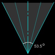
The Apollo astronauts used modified Hasselblad 500/EL cameras fitted with the Zeiss Biogon lens and shooting 70 millimeter film. This particular arrangement produces a field of view with an angular width of 53.5°. Fig. 1 shows what that field of view would look like if made visible and seen from above. At the very bottom of the figure is the camera lens. The dashed vertical line is the optical axis, a line of sight parallel to the axis of the lens. But the field of view contains many other lines of sight -- an infinite number of them, in fact -- and they are not parallel. There is a difference of approximately 27° (half the field of view) between the line of sight at the optical axis and the line of sight at the edge of the field of view. The optical axis corresponds to the point at the exact center of the photograph. In Apollo photographs this corresponds to the central fiducial. A point on the boundary of the field of view would be at the edge of the photo. The dotted lines in Fig. 1 between the boundaries and the optical axis represent other possible lines of sight that would also correspond to certain points on the photograph. They are included to emphasize that lines of sight radiate outward from the focal point, and the resulting photograph will contain all those lines of sight.
Light radiates in all directions from any source of light. The sun is no exception. The sun is so far away from the earth and moon that by the time the light reaches us, it's essentially parallel. If you were standing on the surface of the earth or moon, everything you could see lit by the sun would be illuminated from the same direction.
But not all objects will be seen from the same direction. In the previous section we established that the line of sight varies across the field of view. In Fig. 2 the Apollo lunar surface camera field of view is superimposed on a set of parallel lines representing the parallel light rays from the sun, as seen from above. Pay special attention to how those lines of sight intersect with light rays at various points. Note how in each scenario, different lines of sight intersect with the parallel rays at different angles. The angle formed by the line of sight and the direction of illumination is called the "phase angle", and "phase" here obviously relates to the familiar concept of the phase of the moon. The phase angle determines many things about what a particular object looks like: whether there's a glare from it, how bright it appears, how much of it is lit, etc. Each line of sight in Fig. 2 corresponds to a certain phase angle, since that line of sight will form the same angle with any ray in a set of parallel light rays. Fig. 2 (right) presents an interesting special case. The left boundary is parallel to the light, producing a phase angle of 0°. But at the right boundary there is a phase angle of 53.5°. This is a significant difference.
Prior to the 15th century, artists had difficulty accurately representing the appearance of objects and their relationship to their surroundings.
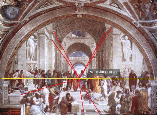
In Fig. 3 the side wall of the illustrated tower recedes from the viewer. The base is drawn at one angle while the balcony and rail of the tower are drawn an an incompatible angle. The eye rejects this as an accurate rendition of the tower. Medieval artists (Brunelleschi is generally credited) eventually discovered the solution. If they extended the parallel lines that receded directly away from the viewer, they discovered they would meet at the horizon at a single point in the horizontal center of the field of view where the distinction between them would vanish. Hence the term "vanishing point" where parallel lines in a field of view will appear to meet. Thereafter they could "construct" a scene by drawing a temporary horizon and a vanishing point and lay out features following those lines. Raphael's "School of Athens" in the Vatican is an excellent example of the simplest version of this so-called linear perspective.
The artistic approach is not just a trick. A geometrical and mathematical transformation relates the conceptual drawings in Fig. 2 with the photograph in Fig. 5. The lines receding from the viewer in Fig. 5 (red annotations) are similar to the parallel lines in Fig. 2 (left). The transverse lines in Fig. 5 -- the front edge of the porch, steps, and roofline -- are analogous to the parallel lines in Fig. 2 (center). Lines exactly perpendicular to the optical axis will not appear to have a vanishing point. But what about Fig. 2 (right)? What if the lines in question aren't aligned with the optical axis or transverse? This was the next step in realistic rendering -- two-point perspective. This is the most common method used by artists today. If you don't look at an object head-on but instead at an angle, each set of parallel lines will have a separate vanishing point.
That's what we see in Fig. 6. The photographer is looking at the corner of the building and both the front wall of the building (red lines) and the side wall (pink lines) recede toward the horizon. Neither vanishing point is at the center of the field of view. And in this case neither vanishing point is within the field of view. This is perfectly allowable and does not violate the theoretical conceptualization. Except for perfectly transverse lines, all sets of parallel lines will have a vanishing point. Examples of perspective can be arbitrarily complex (Fig. 7) because some scenes will have many sets of parallel lines going off in different directions, not always meeting at a vanishing point on the horizon. Those that meet at the horizon, in one- and two-point perspective, are not only parallel to each other, but also to the ground. This includes horizontal rows of windows (Fig. 6), structural beams, and floor panels and tiles (Figs. 4 and 5).
The oft-quoted premise of the conspiracists is:
|

 Parallel light rays must
cast parallel shadows.
Parallel light rays must
cast parallel shadows.
