different shadow lengths


|
|
|
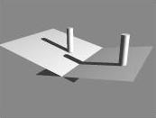
The view in Fig. 2 (right) is from directly overhead and shows clearly that the shadow cast by the cylinder on the "downhill" side is distinctly longer than the other shadow. Note also that the ground exhibits exactly the same kind of variable lighting that we see in the photograph, helping confirm that this (not some mysterious extra light source) is the phenomenon at work, although we note that the variation might also be caused by the astronauts churning up darker subsurface soil.
|
|
|
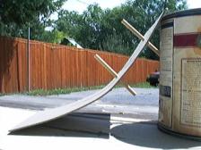
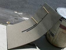
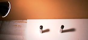
It is propped up to simulate a sun elevation of approximately 10° at a time of day where the sun elevation was some 60°.
In Fig. 4 the line of sight is approximately that of Fig. 1. It can be clearly seen that the shadows are of different lengths. The dowel pin nearest the sun casts a lengthier shadow, just as the up-sun astronaut in Fig. 1 casts a lengthier shadow.
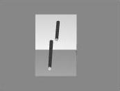
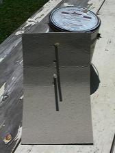
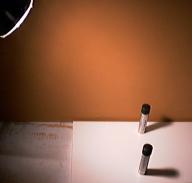
Fig. 5 is the same setup as seen from "above" -- i.e., from what would be overhead were this arranged horizontally. Here all trace of shadow distortion due to curvature vanishes, and the difference in shadow length is most apparent.
 Other frames from the
same film show the astronauts casting shadows of equal length as they
move about. They are obviously moving toward and away from a large
light source. [Mary Bennett and David Percy]
Other frames from the
same film show the astronauts casting shadows of equal length as they
move about. They are obviously moving toward and away from a large
light source. [Mary Bennett and David Percy]
|
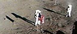
In this case, we consider that the astronaut on the right in Fig. 1 is standing atop a small rise and the astronaut on the left is at a lower elevation, casting his shadow on mostly level ground.
We further consider that one astronaut in Fig. 6 has stepped back away from the flag while the other one has gone some distance away, probably to take photographs. He is no longer on the small rise and is now also casting a shadow onto relatively level ground.
Bennett's and Percy's argument that the shadow lengths are caused by variations in illumination angles due to a nearby (versus infinitely distant) light source would also require the shadows to diverge slightly in the second photograph. But we observe the shadows to be virtually parallel, converging slightly due to the perspective we would expect from such a camera angle. But if Bennett and Percy are correct, the distant astronaut's shadow should point farther away; the shadows should appear to diverge.
|
|
|
|
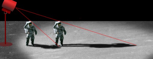
In Fig. 9 the objects are a similar distance from the light, but are separated laterally as theorized by Bennett and Percy to explain Fig. 6. However we can see that the shadows will appear to diverge, whereas in Fig. 6 the shadows appear to converge slightly.
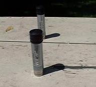
In Fig. 10 the same objects are illuminated by sunlight. They appear very nearly parallel, but actually converge slightly as perspective dictates. Clearly the objects illuminated in sunlight produce shadows closer to those in Fig. 6 than objects illuminated with artificial studio lighting.
Photos of the area show
it to be flat. [Mary Bennett and David Percy]
|
The question to ask is whether we'd see any evidence variation if it really were there. What would be sufficient evidence of terrain variation? We might expect to see variations in the lighting. Terrain less directly lit might appear darker, as we noted above. We might also look for hard-edged discontinuities that represent the crests of rises. We might also look for objects that disappear abruptly as if behind rises. We might also look for shadows that behave a bit differently than expected.
Observing some or all of these would suggest a variation in terrain. But would failing to observe them prove that the terrain was flat? No. In logic this is called the fallacy of inverse implication, encapsulated by the maxim, "Absence of evidence is not evidence of absence." Just because Bennett and Percy fail to observe any expected indicators of slope doesn't mean no such slope exists. There are cases in which the slope exists without exhibiting the most common indicators.
For this specific photo, we note little color variation, no hard-edged discontinuities. It's unclear whether the flag pole disappears behind a rise or simply into the soil.
|
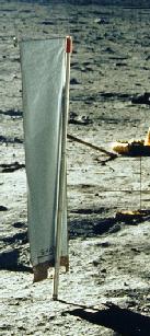
Correctly aligned, the square top should cast a nearly-perfect rectangular shadow. But in the authors' proof photo we see the tip of the collector's shadow become gradually thinner, as if it were falling on a patch of ground sloping away from the camera.
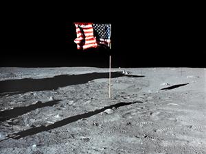
The strongest evidence, however, of irregular terrain is the shadow of the flag and flagpole. They are mostly invisible in Fig. 11 (the authors' version of the photo), but we can examine it more closely in a larger image (Fig. 13).
|
The evidence Bennett and Percy present to establish a planar surface is ironically the best evidence of a non-planar surface. A significant and abrupt change in the angle of the lunar surface can be found in the area onto which the shadows in question are being cast. In fact, the flagpole shadow very closely resembles the simplified computer model in Fig. 2 and the empirical model in Fig. 4. When viewed from a high angle (Fig. 1) shadows cast onto non-planar terrain vary in length, but not necessarily in shape. Linear objects cast apparently linear shadows. But when viewed from a low angle (Fig. 13), such shadows display a change in shape or direction, such as we see in the proof photo. Linear objects cannot cast curved or bent shadows onto a planar surface.
The irregularity in the terrain corresponds exactly to the location in which the variations in shadow length are observed. We further note that the flagpole shadow cannot be produced by any of the hoax methods Percy has suggested, and in fact can only be produced by a lunar surface irregularity. This obvious irregularity has the shape and orientation that would produce the shadows observed in Fig. 1.

